
ديناماس
لا يزال النص الموجود في هذه الصفحة في مرحلة الترجمة إلى العربية. |
ديناماس أو DYNAS ((بالإنجليزية: Dynamic Selectivity)[1][2][3]) هي تقنية ترشيح (تصفية) وضبط تناظرية ديناميكية analog filtering لتحسين استقبال البث الإذاعي FM في ظل الظروف المعاكسة.
نظرة عامة
[عدل]العلامة التجارية[4] DYNAS تعتمد على نفس مبادئ اختيار القناة (In Channel Select (ICS)) لشركة إتش يو سي إليكترونيك H.u.C. Elektronik. صمم المهندس الألماني ينس هانسن Jens Hansen مُرشح التتبع الجديد[2][3] في عام 1982م.[5] حيث وضع نموذج أولي للمفهوم باسم High Select في صيف عام 1983م.[5] بتمويل من صناديق الابتكار في مدينة برلين، غادر هانسن بوش/بلوبونكت للبدء، مع رفيقه كلاوس إمشلير كاتيتو Klaus Müller-Catito، بتأسيس شركته الخاصة إتش يو سي إليكترونيك في عام 1984م.[5][6][7][8][nb 1][nb 2] وعندما فشلت مفاوضات الترخيص مع صاحب العمل السابق،[8] قام بتسويق النظام في أوائل 1990م باسم DYNAS من خلال شركة تليفونكين الإلكترونية Telefunken electronic الألمانية[2] (عرض من إيغ-تليفونكين و داسا)،[9][10][11][12][13][14] التي كانت على صلة مع شركة Telefunken Semiconductors [الإنجليزية][2][3] (اسمها السابق إيغ-تيليفونكين هالبليتيرويرك في هايلبرون)، كما صمم الدوائر المتكاملة لتنفيذ النظام، و TEMIC/TFK[3] يو 4290 ب U4290B (نظام إف إم مستقل له 68 طرف)،[2][3][4][12][15][16][17][18] يو 4291 ب U4291B (مُعالج مُساعد لـDYNAS)[18] و U4292B (نظام DYNAS الذي يُتحكم فيه من خلال البرمجيات).[1][18]
بالمقارنة مع أجهزة الاستقبال التقليدية، فإن نظام DYNAS له اختيارية أفضل بمقدار 26 dBديسيبل، وحساسية أفضل بمقدار الضعف (تحسنت بمقدار 6 dB) وبالتالي مضاعفة مساحة الاستقبال تقريبًا والسماح باستقبال حتى المحطات شديدة الضوضاء.[1] ويتحقق ذلك من خلال النطاق الترددي التكيفي لمرشح التردد الوسيط IF ومن خلال التتبع الديناميكي للتردد المركزي لمرشح IF في الوقت الفعلي.
من الممكن استقبال إشارة صوت مُجسم (استريو) دون إزعاج مع نطاق إرسال يبلغ 200 كيلوهرتز. ولا يزال من الممكن استقبال إشارة أحادية دون أي إزعاج إلى حد كبير بتردد 100 كيلوهرتز.
جرى اعتماد المبدأ في بعض أجهزة ضبط FM المتطورة مثل جهاز ضبط Burmester التناظري 915 (1991م)[19] أو موالفات المزج الرقمي[nb 3] Onkyo Integra T-4970 (عام 1992م)[2][3][16] وجهاز T-488F (عام 1993م)[15][20] وكذلك في أجهزة راديو السيارات المختلفة، مثل Alpine 7619R (عام 1989) وجهاز 1310R/3681 (عام 1990م)،[17] وجهاز JVC KS-CG10 (عام 1992م)،[4] وجهاز Clarion CRX121R (عام 1993م)،[21] وCRX123R (عام 1993)،[21] وCRX121RM[22] وCRX123RM،[22] Gelhard GXR 990S (عام 1993) أو Conrad Soundcraft AR6800 DYNAS،[nb 4] والتي تتأثر بشكل خاص بظروف الاستقبال الصعبة والمتغيرة بسرعة.
تقنيات مماثلة
[عدل]نظام In Channel Select ( ICS ) الذي ابتكرته شركة HuC Elektronik في عام 1984م[5][23][24] هو سلف لنظام DYNAS بشكل أساسي لمستقبلات FM ذات النطاق الضيق.[25][26][27][28] يعتمد على مرشح التتبع High Select (بالألمانية: Mitlauffilter المعروف أيضا باسم MLF) والذي جرى تطويره بواسطة Jens Hansen منذ عام 1982م.[5] ولقد قامت ICS بتحسين الاختيارية بنحو 20 ديسيبل وتحسين الحساسية بحوالي 6 ديسيبل.[25]
هناك تقنية مشابهة جدًا وهي نظام التتبع النشط في الزمن الحقيقي (Active Real-time Tracing System ARTS)، كما جرى تنفيذه في جهاز Pioneer Elite F-91 وبعض إصدارات F-717[nb 5] من أجهزة التوليف المتطورة في عام 1987م.[29][30][31][32][33]
كذلك فإنSuper Sound Tracing ( SST ) هي تقنية مشابهة من إنتاج شركة Sony تؤثر على مرحلة موجة الراديو RF بدلاً من مرحلة IF.[33][34][35] جرى تنفيذ نظام SST رباعي المراحل في الموالفات المتطورة مثل ST-S555ESX (عام 1986م)، وST-S333ESX (عام 1986م)، وST-S444ESX[36]/ST-S700ES (عام 1987م)، وST-S800ES (عام 1987م)[36][37] وST-S333ESX II (عام 1987م)[34][36][38][39] و/ST-S730ES (عام 1988م).[36][39] جرى تنفيذ Advanced SST،[35][40] الذي يقسم نطاق الضبط إلى 32 قسمًا، في بعض المتغيرات النموذجية[nb 6] من ST-S739ES وST-S333ESG (عام 1989م)/ST-S770ES (عام 1990م)[35][36][40][41][42][nb 6] و ST-S333ESA (عام 1991م) و ST-S333ESJ (عام 1993م) وST-S707ES (عام 1993م)[36][43][44][nb 6] وST-SA5ES (عامي 1994م/1996م).[36][45][nb 6]
تعد تقنية Sharx من إنتاج شركة Blaupunkt، والتي جرى تقديمها في عام 1997م في أجهزة راديو السيارات RD 148 في Modena & Lausanne مع "DigiCeiver"، حلاً رقميًا مشابهًا جرى تنفيذه في البرنامج. لا يزال تنفيذ Sharx الأصلي يعتمد على مجموعة من الرنانات الخزفية التناظرية القابلة للتبديل لمرحلة مرشح IF قبل التحويل التماثلي الرقمي A/D لمزيد من معالجة الإشارة في قسم معالجة الإشارات الرقمية DSP. قرابة عام 2000م، انتقل مرشح IF القابل للتبديل إلى المجال الرقمي أيضًا، أي أنه جرى دمجه في شريحة DigiCeiver/TwinCeiver، مما ترك فقط المرحلة الأولى من مرشح IF جزءًا منفصلًا.[46][47]
ملاحظات
[عدل]- ^ تختلف المصادر فيما يتعلق بالتاريخ الدقيق لتأسيس شركة هانسن من صيف 1983 إلى 1984 إلى يونيو 1985.
- ^ في حين أن معظم المصادر تشير إلى اسم الشركة على أنه Hansen & Co.، Hansen/Catito Elektronik، H&C Elektronik أو H.u.C Elektronik GmbH، فإن أحد المصادر يذكر بدلاً من ذلك شركة مقرها برلين تدعى Sico-Elektronic GmbH والتي فازت بجائزة الابتكار في برلين-براندنبورغ لعام 1984 لاختراعها نظام استقبال معزز لإشارات الراديو المعدلة بالتردد.قالب:Citeref (تم تسجيل إحدى براءات اختراع هانسن بواسطة شركة تدعى "Sita Electronik GmbH" [ك].)
- ^ بعض كتالوجات منتجات Onkyo [1] تذكر أن Integra T-9890DSR (1995) تدعم نظام DYNAS أيضًا، ولكن لا يدعم دليل المستخدم أو دليل الخدمة هذا.
- ^ The Conrad Soundcraft AR6800 DYNAS car radio uses a TEMIC Tuner 1310 FAB 3X1 781 module. The unidentified DYNAS chip on the PCB is a glue-top chip on board (COB). [2][3][4]
- ^ Pioneer sold two completely different looking tuners under the F-717 name in 1987: The first one, labelled Digital Synthesizer Tuner F-717 on the front panel as sold in various international markets in 1987, is based on the F-77 (1985) tuner and does not support Active Real-time Tracing System (ARTS). [5][6] It was also sold as F-717L for a version with addition LW band capabilities. [7] The second one, labelled Reference Digital Synthesizer Tuner F-717 on the front, does support ARTS (also labelled as such on the front panel) and was sold at least in Japan in 1987. [8][9][10][11] This is a variant of the F-91 (1987) [12], but features an additional front panel switch to select from two FM antenna inputs at the back.
- ^ ا ب ج د تتبع الصوت الفائق Super Sound Tracing (SST) لم يتم تنفيذه في جميع المتغيرات الخاصة بالطراز المحلي لهذه الموالفات. على سبيل المثال، وفقًا لدليل الخدمة،قالب:Citeref في المملكة المتحدة، AEP، الإصدارات الألمانية والإيطالية من ST-S770ES، تم ترك المساحة الموجودة على PCB لدوائر SST غير مأهولةقالب:Citerefقالب:Citeref وتم تجاوزها على الرغم من إعلان سوني عن ميزة SST للموالف في كتالوجات المنتجات الألمانية حتى منتصف عام 1993.قالب:Citeref يوجد وضع مماثل على الأقل بالنسبة للإصدارات الأمريكية AEP وE وG وI من طراز ST-S707ESقالب:Citerefقالب:Citeref [13][14] and some variants of the ST-SA5ES. [15][16] في حالة ST-SA5ES، يوجد تخطيطان مختلفان تمامًا للوحة الدوائر المطبوعة: الأول مشابه جدًا للسلسلة السابقة (ST-S739ES/ST-S770ES/ST-S707ES و ST-S333ESG/ST-S333ESA/ST-S333ESJ), بينما الثاني تصميم جديد تماما [17] (ولكن مختلف عن ST-SA50ES).
![[1]](https://web.archive.org/web/20210613115959/https://www.hifi-wiki.de/images/f/fb/Onkyo_T-9890_DSR-Prospekt-1995.jpg)
![[4]](https://web.archive.org/web/20170808080050/https://www.mikrocontroller.net/attachment/170376/Tuner_1310.jpg)
![[13]](https://web.archive.org/web/20210612232303/https://i.pinimg.com/originals/b5/eb/ea/b5ebea17cdd32dbd9dbb56d9bc428597.jpg)
![[15]](https://web.archive.org/web/20210613115633/https://bluess.cocolog-nifty.com/labo/images/stsa5es.jpg)
![[16]](https://web.archive.org/web/20210609193356/https://www.fmtunerinfo.com/ST-SA5ESinside.jpg)
المراجع
[عدل]- ^ ا ب ج "U4292B - FM-IF IC for the DYNAS System" (PDF) (datasheet). A1 (ط. preliminary). Heilbronn, Germany: Telefunken Semiconductors / TEMIC TELEFUNKEN microelectronic GmbH. 19 أغسطس 1996. مؤرشف (PDF) من الأصل في 2022-11-01. اطلع عليه بتاريخ 2021-06-07. ص. 1:
U4292B هي دائرة متكاملة لتعديل التردد FM-التردد المتوسط IF ثنائية القطب، والتي يتم التحكم فيها بواسطة برنامج. فهي تقوم بجميع وظائف نظام DYNAS. تم تصميم الجهاز لتطبيقات راديو السيارة وجهاز الاستقبال المنزلي. DYNAS هو نظام جديد تمامًا لمعالجة FM-IF. يستخدم مرشحات تمرير النطاق مع نطاق ترددي يصل إلى حوالي 20 كيلو هرتز مقارنة بـ 160 كيلو هرتز لمرشح تمرير النطاق التقليدي، ويتتبع التردد الرنان إلى التردد الفعلي. تطبيق DYNAS يعزز بشكل كبير كل من الخصائص الأساسية الكلاسيكية لاستقبال الراديو: الانتقائية والحساسية الاستقبال. DYNAS يضمن التعزيز إلى مستويات لم تكن تعتبر حتى الآن ممكنة من الناحية المادية.
Alt URL. - ^ ا ب ج د ه و Maier, Johannes (Dec 1992). F., K.; W., C. (eds.). "Volles Programm: Onkyo T 4970 - Der Goldwäscher für UKW". RadioExtrem. stereoplay (بالألمانية). Stuttgart, Germany: Vereinigte Motor-Verlage. Vol. 1992, no. 12. pp. 18–26 [20–21, 26]. ISSN:0172-388X. pp. 19–20:
Petsuya Toyama, Tunerentwickler von Onkyo [...] Dafür bietet der Newcomer sieben weitere hyperschmale Trennschärfepositionen an. Nach der von dem Berliner Jens Hansen ausgetüftelten Methode [...] stehen die entsprechenden, sich je nach Ernst der Empfangslage stufenweise mehr oder minder verengenden Türchen nicht mehr fest an einer Stelle. Damit die Musik-vermittelnden Frequenzauslenkungen noch durchpassen, versucht ihnen der Wackelschlitz so gut wie möglich zu folgen. Sobald der T 4970 Dynas-(Dynamic-Selectivity-)-Kunststückchen aufführen soll, wird die Zwischenfrequenz von 10,7 Megahertz noch einmal auf eine Lage um 700 Kilohertz umgesetzt. In härtesten UKW-Situationen versuchen dann gleich vier auf "scharf" gestellte, von elektronisch steuerbaren Kapazitätsdioden nachgezogene Schwingkreise den Modulationsschlenkern hinterherzuhechten. Die Abstimmspannung erzeugt sich der von der deutschen Firma Telefunken Electronics hergestellte Dynas-Chip dabei hintenrum, aus dem niederfrequenten Musik-Ausgangssignal. [...] Das klappt aber nur mit dem Mono-Summensignal perfekt, bei Stereo wüßte der arme [68-]beinige Siliziumkäfer ja nicht hü oder hott. Die wirksameren schmaleren Trennschärfetürchen kommen deshalb erst dann zum Einsatz, wenn es aufgrund der Feldstärke und bösartiger Frequenznachbarn ohnehin ratsam wird, auf die unkritische Mono-Wiedergabe umzuschalten. [...]
- ^ ا ب ج د ه و Wienforth, Ulrich (Dec 1992). "Imagepflege - Onkyo verteidigt seine Spitzenstellung: Tuner T-4970". Stereo (بالألمانية). pp. 28–31.
[...] Dann hilft nur noch jene Schaltung, die von einem Berliner Ingenieur entwickelt, von Telefunken als Chip realisiert und von Onkyo jetzt erstmals serienmäßig in einem Heimtuner eingesetzt wurde: Dynas. [...] Der Name steht für "Dynamic Selectivity", also dynamische Trennschärfe. Der Grundgedanke von Dynas ist, das konventionelle, statische Zwischenfrequenzfilter durch einen Mitlauffilter zu ersetzen, das den Frequenzänderungen des UKW-Signals folgt. Ein solches Filter kann entsprechend schmalbandiger sein und verbessert die Trennschärfe. Zusätzlich wird die Filterbandbreite je nach Stärke der störenden Nachbarsender in mehreren Stufen automatisch umgeschaltet. Dazu sind aufwendige Kontrollschaltungen notwendig, die aus dem Dynas-Chip einen veritablen Vielbeiner gemacht haben. [...]
- ^ ا ب ج "5. Block Diagram & 6. Standard Schematic Diagram". JVC Service Manual - CD Changer Control Tuner Deck KS-CG10 B/E/G/GE/GI Digifine (ط. revised G). جيه في سي. مارس 1992. ص. 1, 21–22. No. 49142. مؤرشف من الأصل في 2021-06-14. اطلع عليه بتاريخ 2021-06-14. ص. 1:
[...] DYNAS is a trademark of H.u.C. Ele[k]tronik GmbH [...] The DYNAS system has been modified from the intermediate system. Although the FM P.C. board and parts list are present, any FM adjustment procedure is not described. Until the FM adjustment method is published, therefore, the FM P.C. board should be replaced by the P.C. board ass'y. [...]
(NB. IC801 on the tuner PCB is a 68-pin U4290B.) - ^ ا ب ج د ه "Ungestörter Dialog mit tonangebender Technik". Neue Produkte. Tips Trends Märkte - Das Informationsblatt der Technologie-Vermittlungs-Agentur Berlin (بالألمانية). Berlin, Germany: Technologie-Vermittlungs-Agentur (TVA). Vol. 1984, no. 2. Feb 1984. Archived from the original on 2021-06-10. Retrieved 2021-06-10.
Wer hat sich nicht schon geärgert, wenn er beim Empfang seiner Lieblingssendung auf UKW in den entscheidenden Augenblicken durch überlagerte Nachbarsender gestört wurde. Ähnlich beklagenswert ist es für den Funkamateur, wenn der Empfang von der Großwetterlage abhängt und die atmosphärischen Störungen "Gewitterstimmung" verbreiten. [...] Nach dem Prinzip der Rauschunterdrückung versucht die Industrie daher seit Jahren, die Empfangsqualitäten von Radios und Funkgeräten entscheidend zu verbessern. دولبي und High Com sind Begriffe, mit denen dieses Prinzip bekannt wurde. [...] Für den Neuberliner Hansen und seinen Partner Müller-Catito ist die Leistungsfähigkeit dieser Verfahren auf die Dauer ungenügend. Um erheblich höhere Empfangsempfindlichkeiten und damit stark verbesserte Reichweiten zu erreichen, haben sie das Mitlauffilterverfahren (MLF) "High Select" entwickelt und sich damit selbständig gemacht. Mit diesem neuen Verfahren können Signale empfangen werden, die mit einem üblichen Empfänger nur noch als "Leerlaufrauschen" wahrnehmbar wären. [...] Die völlige Neuentwicklung benutzt anstelle eines in seiner Resonanzfrequenz feststehenden Zwischenfrequenzfilters ein schmalbandiges, in der Resonanzfrequenz steuerbares Filter, wobei die Steuerung dafür sorgt, daß der Filter-Resonanzbereich stets bei der Momentanzwischenfrequenz liegt. Das Ergebnis läßt sich hören. [...] Abschattungen, Reflexionsstörungen, Nachbarkanalstörungen in kritischen Versorgungsgebieten und Grenzempfindlichkeiten sind ausgeschaltet. Selbst völlig verrauschte Signale erklingen klar und deutlich. Die Realisierung des MLF-Verfahrens und die Gründung des eigenen Unternehmens sind das Ergebnis eines mehrjährigen Entwicklungsprozesses. 1982 kam der Erfinder Jens Hansen zur TVA und stellte seine Konzeption mit den durchgeführten grundlegenden Untersuchungen vor. Um den Nachweis der Realisierbarkeit anzutreten, mußte ein Funktionsmodell gebaut werden. Durch die Vermittlung der TVA wurde der Forschungsförderungsfonds des Senators für Wissenschaft und Forschung genutzt. [...] Für die Experten war das Konzept so überzeugend, daß es gefördert wurde. Ein Hochschullehrer der Technischen Fachhochschule Berlin ermöglichte Untersuchungen im Meßlabor. [...] Im Sommer 1983 konnten Hansen/Catito bereits das Funktionsmodell vorstellen, das die gewünschten Eigenschaften aufwies. [...] Dieser Erfolg ermutigte sie, selbst das neue Verfahren in marktfähige Produkte umzusetzen. Mit der TVA stimmten sie die nächsten Schritte ab. Die Unternehmensberatung für die Wirtschaft (ubw) wurde eingeschaltet, um im Rahmen des Förderprogramms "Existenzgründungsberatung" eine Unternehmenskonzeption auszuarbeiten. Mit der Unterstützung der TVA konnte die neue Firma Hansen/Catito Elektronik in das Berliner Innovations- und Gründerzentrum (BIG) einziehen. [...] Im Rahmen des Modellversuchs "Förderung technologieorientierter Unternehmensgründungen" wurde ein Antrag auf Förderung beim VDI TZ gestellt, um die Existenzgründer beim Aufbau eines eigenen Produktions- und Vertriebssystems zu unterstützen. [...] Hansen/Catito Elektronik - ein Beispiel für eine eindrucksvolle Initiative aus Berlin.
- ^ Freeman، Clive (8 أبريل 1986). كتب في Berlin, Germany. "High-Technology Investment Revitalizes Berlin - A Special Report on West Germany". انترناشيونال هيرالد تريبيون - Published with the New York Times and The Washington Post. Paris, France. ج. 15/86 رقم 32,076. ص. 12. ark:/13960/t88h3n32z. ص. 12:
Two years ago, Jens Hansen, 42, a telecommunications engineer, won the Berlin Innovation Prize for inventing an enhanced reception system for frequency modulated signals. [...] Spurred by the award, he and Klaus Müller-Catito, a close colleague, launched H & C Electronics last June in the Ackerstrasse complex. His staff of seven produce accessory devices for radio systems, VHF units and satellite receiving systems. "We are small at present but growing rapidly," said Mr. Hansen, who formerly worked for Bosch in Berlin as a research engineer.
- ^ Ronzheimer, Manfred; Heller, Frank, eds. (15 Jul 2000) [1998]. "Innovationspreis Berlin-Brandenburg: Liste der Preisträger 1984–1994". Innovationspolitik (بالألمانية). BerliNews. Archived from the original on 2000-09-03.
[...] 1984 [...] System für die Erhöhung und Erweiterung der Frequenzmodulation im UKW-Bereich [...] Sico-Elektronic GmbH [...] Gustav-Meyer-Allee 25, 13355 Berlin [...] Herr Jens Hansen [...] Tel. 030/ 46 320 38, Fax 030/ 46 307 300 [...]
- ^ ا ب rotterle64 (16 Jun 2005) [2005-06-15]. "Re: "Scheunentor"-Empfänger schlägt Dynas". www.rundfunkforum.de (بالألمانية). Archived from the original on 2021-06-09. Retrieved 2021-06-10.
[...] es ein dynamischer ZF-Filter. Dynas ändert aber nicht nur seine Bandbreite[,] sondern auch seine Durchlaßfrequenz. Zuerst wird die ZF von 10,7 MHz auf 700 kHz heruntergemischt. Danach wird das Signal durch 4 LC-Kreise gefiltert [...] Durch zugeschaltete Widerstände können die LC-Kreise bedämpft werden[,] d.h. ihre Bandbreite wird größer. Mit diesen Filtern läßt sich eine Bandbreite bis [...] runter zu 10–15 kHz realisieren. Da diese Bandbreite nicht für UKW-Rundfunk reicht, müssen die Filter [...] nachgeregelt werden. Dies geschieht mittels Kapazitätsdioden. Die Steuerspannung dafür wird aus dem Mono-NF-Signal gewonnen. Dessen augenblicklicher Wert steht im direkten Zusammenhang mit der aktuellen Frequenz der ZF. Die Filter werden mit einer geringen Verzögerung nachgeführt. Ein normaler 85 kHz ZF-Filter dämpft einfach die Störungen[,] aber auch das Nutzsignal. Dynas hingegen läßt das Nutzsignal (Monosignal) komplett durch. Bei geringen NF-Pegeln grenzt es so die Störungen perfekt aus, bei hohen NF-Pegeln müssen die Filter so stark auslenken[, daß] auch Teile der Störfrequenzen mit durch kommen. Letztendlich hängt die Trennschärfe von Dynas also vom Programminhalt des Senders ab. Die heutige Dynamikkompression bei den Sendern ist da ungünstig für Dynas. [...] In einer Zeitschrift (AutoHifi), die [19]91/[19]92 herum Dynas noch als Prototyp vorstellte, stand drin, dass Dynas von einem ehemaligen Mitarbeiter von Blaupunkt, der eine eigene kleine Firma gegründet hatte, entwickelt bzw. heraus gebracht wurde. Die haben damals oder kurze Zeit später auch verschiedene Hersteller befragt[,] ob sie Dynas einsetzen wollen. [...]
{{استشهاد ويب}}: صيانة الاستشهاد: أسماء عددية: قائمة المؤلفين (link) - ^ McLeod، Gordon Richard (يناير 1992) [1991-12-06]. "DYNAS-dynamic FM filter system". IEE Colloquium on Vehicle Audio Systems. London, UK: معهد الهندسة والتقانة (IET): 4/1–4/3. S2CID:109889981. مؤرشف من الأصل في 2022-04-08.
The DYNAS system features an approach which many would consider to be physically impossible: the reception of a broadband transmission spectrum via narrowband filters. This principle seems self-contradictory at first consideration; at any rate, specialists could all easily agree that it does, however, satisfy many of the most critical needs and requirements actually encountered in receiving operations. The following are, of course, the advantages of broadband transmission: high signal-to-noise ratios, high dynamics, and a broad audio-frequency spectrum. The DYNAS principle would couple the above advantages with the following benefits of narrowband transmission: great reception sensitivity, and great immunity to interference. The DYNAS principle would, in addition, eliminate the following disadvantages: relative great susceptibility to interference, and poor signal quality. The above advantages, needs, and requirements are in fact implemented by DYNAS by the technique of dynamic selectivity.
[18] - ^ DYNAS system and its application in car radios (report). TEMIC Telefunken microelectronic. يناير 1992 [1989-12-14]. WO 89/12353 A1. (See also: WO89/12353)
- ^ "Das DYNAS-Empfangskonzept". radio fernsehen elektronik (rfe) (بالألمانية). Berlin, Germany: Verlag Technik GmbH / Huss-Medien GmbH. Vol. 41, no. 2. Feb 1992. pp. 88–90. ISSN:1436-1574. قالب:CODEN. (3 pages)
- ^ ا ب Herchner, Dieter (24 Apr 1997) [1993-09-25]. "Verfahren zur Steuerung eines FM-Empfängers mit nachführbarem ZF-Filter und Schaltungsanordnung zur Durchführung des Verfahrens" [Method for controlling an FM receiver with a trackable IF filter and circuit arrangement for carrying out the method] (بالألمانية والإنجليزية). Heilbronn, Germany: TEMIC Telefunken Microelectronic GmbH. Patent DE4332767C2. Archived from the original on 2021-06-11. Retrieved 2021-06-10. [19][20]
- ^ Hansen, Jens (15 Dec 1993) [1989-05-30]. "FM-Empfangsteil" [FM receptor unit] (PDF) (بالألمانية والإنجليزية والفرنسية). Berlin, Germany: H.u.C. Elektronik GmbH. Patent EP0436542B1. WO 89/12353 (14.12.89 89/29). Archived (PDF) from the original on 2021-06-11. Retrieved 2021-06-08. [21][22] (36 pages) (See also: WO 89/12353 A1)
- ^ Rudolph, Dietmar (31 Jan 2009). "Das InChannelSelect Verfahren für UKW-FM". www.radiomuseum.org (بالألمانية). Archived from the original on 2021-06-10. Retrieved 2021-06-10. [23]
- ^ ا ب Onkyo Service Manual Synthesized FM Stereo/AM Tuner Model T-488F - Black and Silver models. Tokyo, Japan: Onkyo Corporation. ص. 3, 6–7, 10–11, 19–24 [10–11, 19, 21, 24]. Ref. No. 3441. PN0M3441 A209. مؤرشف من الأصل في 2022-04-07. اطلع عليه بتاريخ 2021-06-12. (26 pages) (NB. The 68-pin PLCC IC Q851 on U2, the Digital Circuit PCB (NADG-4605-1, 1A404505-1), of this tuner is a TEMIC U4290B (Onkyo Part. No. 22240641).
- ^ ا ب Onkyo Service Manual Synthesized FM Stereo/AM Tuner Model T-4970 - Black and Silver models. Tokyo, Japan: Onkyo Corporation. ص. 3, 6–7, 10–11, 19–24 [10–11, 19, 21, 24]. (26 pages) (NB. The 68-pin PLCC IC Q851 on U2, the Digital Circuit PCB (NADG-4605-1, 1A404505-1), of this tuner is a TEMIC U4290B.
- ^ ا ب Alpine Service Manual: Digital FM/MW/LW/RDS Tuner & CD Shuttle Controller 1310R. Alpine Electronics. ص. 24, 28. مؤرشف من الأصل في 2024-07-07. اطلع عليه بتاريخ 2021-06-12. (65 pages) (NB. The Alpine 1310R uses a 6-pin module FE002 (Part No. 77B50045W01), called DYNAS unit MB3R101A, which contains a U4290B chip (IC3001).)
- ^ ا ب ج "Radio/Audio". TEMIC Integrated Circuits (PDF) (بالإنجليزية واليابانية). TOKO. pp. 56–57 [56]. Archived from the original (PDF) on 2022-09-08. Retrieved 2021-06-12. p. 56:
[...] U4290B-CP FM IF for Dynas System [...] U4291B-FP Coprocessor for Dynas [...] U4292B-FS Soft Dynas [...]
- ^ "Tuner Reviews A-C: Burmester 915 (1991)". Tuner Information Center. 2020 [2001]. مؤرشف من الأصل في 2021-06-10. اطلع عليه بتاريخ 2021-06-10.
- ^ "Onkyo Tuners: Onkyo T-488F (1993) / Onkyo T-4970". Tuner Information Center. 2020 [2001]. مؤرشف من الأصل في 2021-06-10. اطلع عليه بتاريخ 2021-06-10.
- ^ ا ب clarion Service Manual: RDS-EON/FM MPX/MW/LW Radio Cassette Combination With CD Changer Control Model CRX123R (PE-9806A) / CRX121R (PE-9825A). Tokyo, Japan: Clarion Co., Ltd., Service Information Section. ص. 2–3. مؤرشف من الأصل في 2022-04-08. اطلع عليه بتاريخ 2021-06-14.
- ^ ا ب clarion Service Manual CRX123RM / CRX121RM. Tokyo, Japan: Clarion Co., Ltd., Service Information Section. مؤرشف من الأصل في 2024-07-10. اطلع عليه بتاريخ 2021-06-14. (NB. The Clarion CRX121RM and CRX123RM utilize a 68-pin U2490B-B (IC601) on the main PCB.)
- ^ Hansen, Jens & Co. (20–21 Sep 1986). "31. Weinheimer UKW Tagung - Skriptum der Vorträge". In Steger, Stefan & Bahner, Helmut (eds.). UKW-Tagung Weinheim (بالألمانية). Weinheim, Germany: Deutscher Amateur Radio Club e.V. (DARC) Ortsverband Weinheim / Funkamateur-Club Weinheim e.V. (FACW). Vol. 31. pp. 84–90. (7 of 183 pages)
- ^ Schwarzbeck, Günter [بالألمانية]. "Verbesserung der Empfangseigenschaften von Schmalband-FM-Empfängern (ICS-Verfahren)" (PDF) (بالألمانية). Schönau-Altneudorf, Germany. Archived (PDF) from the original on 2021-04-11. Retrieved 2021-06-08. [24] (4+2 pages)
- ^ ا ب ICS - In-Channel-Select - das Empfangssystem der Zukunft / ICS-Restsignalverstärker (product flyer and manual) (بالألمانية). Berlin, Germany: H.u.C. Elektronik / Hansen & Co. Archived from the original on 2021-06-11. Retrieved 2021-06-11. (3+7 pages, page 6 missing)
- ^ Hawker، Pat، المحرر (يونيو 1987). "In-channel-select fm threshold extension". Technical Topics. RADio COMmunication (Radcom) - Journal of the Radio Society of Great Britain. Potters Bar, Herts, UK: Radio Society of Great Britain (RSGB). ج. 63 ع. 6: 406–412 [407]. ark:/13960/t9c58sk9x. ص. 407:
Erwin David [...] draws attention to a قالب:Citeref for the East Kent Radio Society's Carrier newsletter, based on an item by [Dick W. Rollema] in قالب:Citeref. This describes a new "in-channel-select" (ics) technique that can significantly improve the sensitivity and selectivity of vhf/uhf fm receivers. A commercial "blackbox" adapter is being made and marketed by the German firm H&C Ele[k]tronik Hansen & Co of Berlin, which is claimed to improve the s:n ratio of weak fm signals by 6 dB and rejection of in-channel splatter from stronger adjacent-channel signals by some 20 dB. [...] the ics technique appears to be a form of threshold-extension demodulation, as originally developed for professional reception of weak satellite signals, but implemented in a form suitable for use with typical amateur radio fm transceivers. The German unit [...] features a very narrow voltage-controlled filter that automatically tracks the fm signal. For 145 MHz (25 kHz channelling) the filter bandwidth is only 1,800 Hz, ie about one-tenth of the usual i.f filter bandwidth. The receiver's fm detector output voltage, proportional to the instantaneous deviation, steers the ics filter so that it tracks the incoming signal. In demonstrations at a Dutch/German hamfest last year, [Rollema] reports that audibility of weak signals was improved by the unit from Q1 to Q4, though never completely to Q5. For strong signals it is usually advisable to switch threshold-extension demodulators out of circuit. The German hardware is being offered primarily as an external unit for base-station receivers, although the principle can be applied to mobile receivers. A threshold extension demodulator does not, of course, improve the front-end noise factor of a receiver, but there is no doubt that the technique does make it possible to copy signals that would otherwise be unintelligible. It certainly seems a development worth keeping in mind.
[25] - ^ Carlsson, Claes (Sep 1988). Written at Årby Fogdö, Strängnäs, Sweden. "ICS - Vad är det?" [ICS - What is that?] (PDF). QTC - Organ för Föreningen Sveriges Sändareamatörer (بالسويدية). Farsta, Stockholm, Sweden: Föreningen Sveriges Sändareamatörer (SSA). Vol. 60, no. 9. pp. 416–417. ISSN:0033-4820. Archived (PDF) from the original on 2021-06-11. Retrieved 2021-06-11. (2 pages)
- ^ Hansen, Jens; Schwarzbeck, Günter [بالألمانية] (5 Jan 2008). Bopp, Matthias (ed.). "Das In-Channel-Select System" (PDF) (بالألمانية). Langenbrettach, Germany. Archived (PDF) from the original on 2021-04-11. Retrieved 2021-06-08. (1+3+6+6+1+13 pages) [26]
- ^ "11. Circuit description - 11.1. New IF system principle". F-91 FM/AM Digital Synthesizer Tuner - Service Manual (PDF) (بالإنجليزية والفرنسية والإسبانية). Tokyo, Japan / Long Beach, USA: Pioneer Electronic Corporation. Aug 1987. pp. 35–38 [37–38]. Order No. ARP1465. Archived (PDF) from the original on 2021-04-11. Retrieved 2021-06-10. p. 37:
[...] In the case of [the] conventional system, [the] signal pass[es] through the filter without generat[ing] distortion [...] filter is wide. At this time, the system is affected by undesired signal. In the case of [the] new system, [the] signal pass[es] through [...] [a] narrow filter follow[ing] the signal. [...] the system is not affected by undesired signal. This system's filter is controlled by feed[-]forward control, therefore, [the] stability is very high and [there is] no [...] oscillation. This system [implements a] follow[-]type filter so that [the] input FM signal frequency controlled for center of the filter at any time. ([In a] conventional system, [the] filter is followed the input signal.) [...] [The] system [...] consists of the control block and filter block. [The] control block [...] consists of [a] band pass filter [...], FM detector [...] and low-pass filter [...] The band-pass filter [...] has the same characteristic as conventional tuner's narrow filter, and this filter has selective characteristic sufficiently. When FM signal is inputed, FM signal is detected by FM detector [...] after pass through the band-pass filter [...] then, output signal of FM detector [...] is cut the useless high-frequency elements by low-pass filter [...] Filter block [...] consists of two mixer [...] band-pass filter [...] and VCO. Mixer [...] perform frequency change so that multiply input FM signal by VCO output. F-91 introduce the secondary IF frequency as 13.45 MHz. Band-pass filter [...] has the same narrow bandwidth characteristic as the band-pass filter [...] This filter (BPF2) cut the obstruction wave including input signal. Input signal of passed through the band-pass filter (BPF2) is multiplied by VCO output at mixer [...] again, then change to the original frequency. Original signal is detected by FM detector [...] then audio output is obtained. In this way, in spite of use the filter of fixed the center frequency, F-91 operate to the variable filter so that center frequency follow the input signal as equivalent. [...]
[27][28] (4 of 40 pages) - ^ كتب في Tokyo, Japan. High-Fidelity Home-Entertainment - Audio & Video - Components & Systems (Exchange catalog for military). Germany: Pioneer Electronic Corporation / Pioneer Electronic GmbH. يونيو 1987. 50,000-KL(F)280-6-87. مؤرشف من الأصل في 2021-06-09. اطلع عليه بتاريخ 2021-06-11 – عبر Deutsches Hi-Fi-Museum.
[...] ARTS Cleans Up Your Act [...] Pioneer's new Active Real-Time Tracing System - ARTS for short - helps the F-91 deliver clean and optimum signal reception. It replaces the "WIDE/NARROW" filtering technique in which the WIDE position provided better sound quality at the expense of selectivity and, conversely, the NARROW position provided better selectivity at the expense of sound quality (see oscillophotos). Using a kind of "servo-filtering", its IF filter circuit "tracks" the tuned frequency in real time, eliminating interference ONLY where it actually exists, thus providing optimum sound quality AND selectivity. [...] F-91 - Reference Digital Synthesizer Tuner [...] Pioneer's ARTS (Active Real-Time Tracing System): Tuned frequency is followed in real time by IF filter circuit to eliminate interference and pass on purest possible signal to audio output. [...]
- ^ Feldman، Leonard (أغسطس 1988). "Pioneer Elite F-91 Tuner" (PDF). Audio (review). Hachette Filipacchi Media U.S. ص. 58–60, 62, 67 [59]. مؤرشف (PDF) من الأصل في 2019-04-19. اطلع عليه بتاريخ 2021-06-10. ص. 59:
[...] an FM i.f. circuit that has been given the acronym ARTS (for Active Real-time Tracing System). This system eliminates the need for choosing between narrow and wide i.f. bandwidths. Pioneer states that it actively follows the selected signal to provide both the lower distortion normally resulting from wide bandpass and the high selectivity of narrow bandpass. I gathered that the system dynamically tailors bandwidth to the instantaneous modulation of the incoming signal. [...] I also saw evidence that the r.f. section has some capability of tracking the signal; even when my FM signal generator was deliberately detuned from the frequency indicated on the F-91's display, minimum distortion and perfect center tuning were maintained. [...]
- ^ "Pioneer Tuners: Pioneer F-91 (1987)". Tuner Information Center. 2020 [2001]. مؤرشف من الأصل في 2021-04-11. اطلع عليه بتاريخ 2021-06-10.
- ^ ا ب Rich، David Arthur؛ Modafferi، Richard Thomas (Winter 1995–1996). "FM Tuners: The Present State of the Art of FM Reception" (PDF). The Audio Critic. Quakertown, Pennsylvania, USA: Critic Publications, Inc. ع. 23. ص. 43–64 (PDF:39–56) [56 (PDF:48)]. ISSN:0146-4701. 0-74470-82057-4-51. مؤرشف (PDF) من الأصل في 2011-07-16. اطلع عليه بتاريخ 2021-06-10. ص. 56–57 (PDF:48–49):
[...] Pioneer came up with a very innovative solution to the "narrow filters distort the signal" problem. They used this solution in the F-91 tuner. It is such a good idea that it could have gotten someone a Ph.D. (Indeed, a related concept did get someone a Ph.D.—see [Rich 1991].) What the engineers at Pioneer observed was that, although the spectrum of an FM signal is wide when averaged over time, at any instant in time the signal has just one spectral line at the instantaneous frequency. So, if you build a time-varying filter with a very narrow band-width that moves with the instantaneous frequency of the desired signal, then you can eat your cake and have it too. The very narrow bandwidth removes the interferers, but the time-varying nature of the filter insures that the FM signal is not distorted. To move the filter around, a complete auxiliary IF strip designed in the conventional manner and a PLL FM detector are required. We now have a chicken and egg problem, since the conventional receiver has to place the passband of the time-varying filter in the correct place. This is what limits the performance of the system. One very interesting (at least to this author) variation on this is to replace the bandpass filter with a notch filter. Then the stronger signal is removed, but a weaker cochannel interfering signal may now be revealed. Further information on this is in—you guessed it—[Rich 1991]. [...] سوني uses a variation on the tracking-filter theme that involves dynamically varying the position of the RF and mixer filters in response to the signal level at the output of the FM demodulator (which represents how far the instantaneous frequency has moved from the carrier frequency). This is easier to implement in the RF and mixer stages than in the IF because these filters are already tunable. One would think the large signal delay in the IF strip and detector would prevent this from working well, but Sony is shipping tuners with this thing, so it must do something positive. [...]
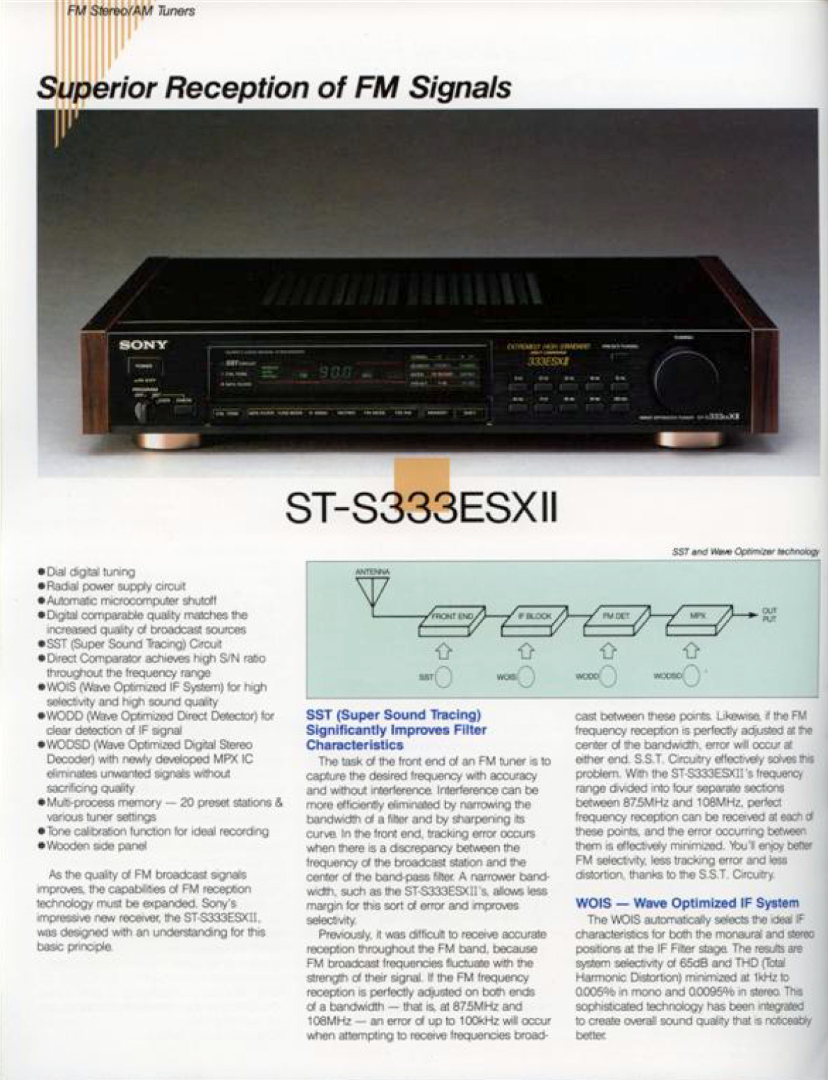
- ^ ا ب "ST-S333ESXII: Superior Reception of FM Signals". FM Stereo/AM Tuners (product catalog). سوني. مؤرشف من الأصل في 2021-06-16. اطلع عليه بتاريخ 2021-06-16.
[...] SST (Super Sound Tracing) Significantly Improves Filter Characteristics [...] The task of the front end of an FM tuner is to capture the desired frequency with accuracy and without interference. Interference can be more efficiently eliminated by narrowing the bandwidth of a filter and by sharpening its curve. In the front end, tracking error occurs when there is a discrepancy between the frequency of the broadcast station and the center of the band-pass filter. A narrower band-width, such as the ST-S333ESXII's, allows less margin for this sort of error and improves selectivity. Previously, it was difficult to [achieve] accurate reception throughout the FM band, because FM broadcast frequencies fluctuate with the strength of their signal. If the FM frequency reception is perfectly adjusted on both ends of a bandwidth - that is, at 87.5 MHz and 108 MHz - an error of up to 100 kHz will occur when attempting to receive frequencies broadcast between these points. Likewise, if the FM frequency reception is perfectly adjusted at the center of the bandwidth, error will occur at either end. S.S.T. Circuitry effectively solves this problem. With the ST-S333ESXII's frequency range divided into four separate sections between 87.5 MHz and 108 MHz, perfect frequency reception can be [achieved] at each of these points, and the error occurring between them is effectively minimized. You'll enjoy better FM selectivity, less tracking error and less distortion, thanks to the S.S.T. Circuitry. [...] WOIS - Wave Optimized IF System [...] The WOIS automatically selects the ideal IF characteristics for both the monaural and stereo positions at the IF Filter stage. The results are system selectivity of 65 dB and THD (Total Harmonic Distortion) minimized at 1 kHz to 0.005% in mono and 0.0095% in stereo. This sophisticated technology has been integrated to create overall sound quality that is noticeably better. [...]
- ^ ا ب ج "Großer Empfang. Sonys Tuner-Technik". SONY Programm '92 (بالألمانية). Cologne, Germany: Sony Deutschland GmbH. Mar 1992. pp. 130–132. p. 130:
[...] WOIS (ZF mit optimierter Filtercharakteristik) [...] Um eine optimale Signalverarbeitung zu gewährleisten, sind für Mono- und Stereo-Rundfunksignale unterschiedliche Filtercharakteristiken im Zwischenfrequenzverstärker erforderlich. Die WOIS-Technik selektiert automatisch die entsprechende Charakteristik und sorgt so bei Stereo- und Mono-Empfang für die jeweils optimale Selektivität, d.h., daß auch eng benachbarte Sender sauber voneinander getrennt werden. Das verbesserte Gruppenlaufzeitverhalten und das linearisierte Amplitudenverhalten reduzieren die Verzerrungen und tragen zur Klangoptimierung bei. [...] SST (Super Sound Tracing) [...] Die wichtigste Anforderung an einen Tuner ist der präzise Empfang der jeweils eingestellten Frequenz. Sonys SST-Technik stellt die Bandbreite der Eingangsstufe exakt auf die Empfangsfrequenz ein und verbessert so die Trennung des Nutzsignals von störenden benachbarten Senderfrequenzen. Diese verbesserte Vorselektion sorgt für störungsfreien Empfang. [...]
(218 pages + technical data and pricelist inlays) (NB. This 1992 product catalog describes the SST technology, and explicitly lists SST as a feature of the ST-S770ES, but also shows a photo of an opened ST-S770ES where the "Advanced SST" section is unpopulated on the PCB. While the 1993 catalog no longer describes SST, it is still listed as a feature of the ST-S770ES, until the tuner was replaced by its successor model, the ST-S707ES, in the subsequent 1993/1994 catalog.) - ^ ا ب ج د ه و ز "Sony Tuners: Sony ST-S333ESXII / Sony ST-S444ESX / Sony ST-S500ES (1987) / Sony ST-S700ES(1987) / Sony ST-S707ES (1995) / Sony ST-S730ES (1988) / Sony ST-SA5ES (1996)". Tuner Information Center. 2020 [2001]. مؤرشف من الأصل في 2021-06-09. اطلع عليه بتاريخ 2021-06-10.
- ^ Sony ST-S800ES Service Manual - AEP Model / G-AEP Model (PDF) (بالإنجليزية والفرنسية والألمانية). سوني. Archived (PDF) from the original on 2019-12-31. Retrieved 2021-06-12.
- ^ "SONY ST-S333ESXII". nice.kaze.com (باليابانية). 18 Mar 2006. Archived from the original on 2021-06-10. Retrieved 2021-06-10.
- ^ ا ب Sony Service Manual FM Stereo/FM-AM Tuner ST-S333ESXII/ST730ES - US Model, AEP Model, UK Model / E Model (بالإنجليزية والفرنسية والألمانية). Sony Corporation, Audio Group, A/V Engineering Service Department. 9-953-824-11. Archived from the original on 2024-07-07. Retrieved 2021-06-12. (34 pages)
- ^ ا ب jomol (31 Jan 2020). "SONY ST 770 Tuner: SST nachrüsten?". hifi-forum.de (بالألمانية). Archived from the original on 2024-11-23. Retrieved 2021-06-12. [29][30]
- ^ "Photo of German Sony ST-S770ES PCB". مؤرشف من الأصل في 2022-04-08. اطلع عليه بتاريخ 2021-06-12.
- ^ Service Manual FM Stereo / FM-AM Tuner ST-S770ES - AEP Model / UK Model. Sony Corporation, Audio Group / Customer Relations and Service Group. سبتمبر 1991. ص. 8–9, 11, 18–23 [18–19, 21]. 9-956-628-11. 91I0850-1. (40 pages) (NB. This service manual, which covers the UK, AEP, German and Italian model variants shows PCBs and schematics with SST not populated.)
- ^ Sony Service Manual FM Stereo/FM-AM Tuner ST-S707ES - AEP Model, E Model, G Model, I Model (بالإنجليزية والفرنسية والألمانية). Archived from the original on 2022-04-08. Retrieved 2021-06-16. (NB. These model variants do not implement SST.)
- ^ Sony Service Manual FM Stereo/FM-AM Tuner ST-S707ES - US Model (بالإنجليزية والفرنسية والألمانية). Archived from the original on 2021-06-16. Retrieved 2021-06-16. (NB. This model variant does not implement SST.)
- ^ "SONY ST-SA5ES". nice.kaze.com (باليابانية). 14 Feb 2008. Archived from the original on 2021-04-11. Retrieved 2021-06-10.
- ^ "DigiCeiver: Blaupunkt car audio delivered carriage-free to your home - Blaupunkt digiceiver technology". Blue Spot Car Audio. Blaupunkt. 2000. مؤرشف من الأصل في 2000-01-26.
- ^ "Blaupunkt car audio delivered carriage-free to your home - DigiCeiver technology". Blaupunkt. 8 يوليو 2009. مؤرشف من الأصل في 2009-07-08.
![[29]](http://bilder.hifi-forum.de/max/952985/esa_990635.jpg)
![[30]](http://bilder.hifi-forum.de/max/952985/fullsizeoutput-76d_990594.jpg)
قراءة إضافية
[عدل]- U4290B (datasheet). Heilbronn, Germany: Telefunken Semiconductors / TEMIC TELEFUNKEN microelectronic GmbH.
- U4291B (datasheet). Heilbronn, Germany: Telefunken Semiconductors / TEMIC TELEFUNKEN microelectronic GmbH.
- Rudolph, Dietmar (9 Nov 2016). "FM-Demodulation: weniger bekannte Verfahren - FM Radios mit Frequenz-Gegenkopplung". Radiomuseum (بالألمانية). Archived from the original on 2021-06-14. Retrieved 2021-06-14.
- "FM-ZF-Filter: In-Channel-Select (ICS)" [FM IF filter: In Channel Select (ICS)]. Funkschau (بالألمانية). Munich, Germany: Franzis-Verlag GmbH. Vol. 58, no. 14. 4 Jul 1986. pp. 35–. ISSN:0016-2841.
- Hansen, Jens (Dec 1991). "In der Spur des Nutzsignals". Funkschau (بالألمانية). Munich, Germany: Franzis-Verlag GmbH / WEKA Holding. Vol. 63, no. 25. pp. 74–77. ISSN:0016-2841.
- "(unknown)". Autohifi (بالألمانية). Weka Media Publishing GmbH. 1991.
{{استشهاد بمجلة}}: الاستشهاد يستخدم عنوان عام (help) - "(unknown)". stereoplay (بالألمانية). Stuttgart, Germany: Vereinigte Motor-Verlage. Vol. 1991, no. 7. Jul 1991. ISSN:0172-388X.
{{استشهاد بمجلة}}: الاستشهاد يستخدم عنوان عام (help) - "(unknown)". CQ DL. Deutscher Amateur Radio Club e.V. (DARC). ج. 58 رقم 11. نوفمبر 1986. ص. inlet 18–19. ISSN:0178-269X.
{{استشهاد بمجلة}}: الاستشهاد يستخدم عنوان عام (مساعدة) - "(unknown)". CQ DL. Deutscher Amateur Radio Club e.V. (DARC). ج. 59 رقم 1. يناير 1987. ص. 6–9. ISSN:0178-269X.
{{استشهاد بمجلة}}: الاستشهاد يستخدم عنوان عام (مساعدة) - Rollema, Dick W. (Nov 1986). "(unknown)". Electron (بالهولندية). Vereniging voor Experimenteel Radio Onderzoek Nederland (VERON). Vol. 41, no. 11. ISSN:0013-4767.
{{استشهاد بمجلة}}: الاستشهاد يستخدم عنوان عام (help) - David، Erwin (1986–1987). "(unknown)". Carrier. East Kent Radio Society (EKRS).
{{استشهاد بخبر}}: الاستشهاد يستخدم عنوان عام (مساعدة) - Bell، David Arthur (1 نوفمبر 1942) [August 1942]. "Reduction of Band Width in F.M. Receivers" (PDF). Wireless Engineer - The Journal of Radio Research & Progress. London, UK: A. C. Cossor Limited, Research Department / Iliffe & Sons Ltd.. ج. XIX ع. 230: 497–502. ISSN:0268-6465. OCLC:183317383. مؤرشف (PDF) من الأصل في 2021-03-09. اطلع عليه بتاريخ 2021-06-16. ص. 497:
This paper discusses the possibility of using a high degree of negative feed-back of frequency modulation in the I.F. section of a frequency modulation receiver, for the purpose of (a) minimising the necessary I.F. band width and (b) making the detected output independent of amplitude without the use of an amplitude-limiter in the I.F. amplifier.
(6 pages) - Panter، Philip F. (1965). Modulation, Noise, and Spectral Analysis: Applied to Information Transmission (ط. 1). New York, USA: McGraw-Hill Book Co., Inc. ISBN:0-07048446-5. OCLC:565424. S2CID:106666863. (ردمك 978-0-07048446-7). (viii+750+9+v pages)
- Nyquist، Harry. (unknown). British Patent No. 531779.
{{استشهاد بكتاب}}: الاستشهاد يستخدم عنوان عام (مساعدة) - Carson، John Renshaw (3 يوليو 1939). "Frequency-Modulation: Theory of the Feedback Receiving Circuit". Bell System Technical Journal. ج. 18 ع. 3: 395–403. DOI:10.1002/j.1538-7305.1939.tb03584.x. ISSN:0005-8580. ark:/13960/t51g21662. اطلع عليه بتاريخ 2021-06-16. (9 pages) [31]
- Chaffee، Joseph G. (3 يوليو 1939). "The Application of Negative Feedback to Frequency-Modulation Systems". Bell System Technical Journal. ج. 18 ع. 3: 404–437. DOI:10.1002/j.1538-7305.1939.tb03585.x. ISSN:0005-8580. S2CID:51659322. ark:/13960/t3qv4v85m. اطلع عليه بتاريخ 2021-06-16. (34 pages) [32]؛ Chaffee، Joseph G. (مايو 1939). "The Application of Negative Feedback to Frequency-Modulation Systems". Proceedings of the I.R.E. ج. 27 ع. 5: 317–331. DOI:10.1109/JRPROC.1939.228396. ISSN:0096-8390. OCLC:1753246. S2CID:109993045. مؤرشف من الأصل في 2022-04-07. اطلع عليه بتاريخ 2021-06-16. (15 pages) (NB. Presented before the New York Section of the I.R.E. on 1939-05-03.)
- Chaffee، Joseph G. (30 مارس 1937) [1936-03-26]. كتب في Hackensack, New Jersey, USA. "Reception of frequency modulated waves". New York, USA: Bell Telephone Laboratories, Incorporated. Patent US2075503. مؤرشف من الأصل في 2022-04-07. اطلع عليه بتاريخ 2021-06-16. (7 pages) [33]
- Roberts، J. H. (نوفمبر 1968). "Dynamic tracking filter as a low-threshold demodulator in f.m. f.d.m. satellitesystems". Proceedings of the Institution of Electrical Engineers. ج. 115 ع. 11: 1597–1606. DOI:10.1049/piee.1968.0280. ISSN:0020-3270.
- Roberts، J. H. (نوفمبر 1968). "Frequency-feedback receiver as a low-threshold demodulator f.m. f.d.m. satellite systems". Proceedings of the Institution of Electrical Engineers. ج. 115 ع. 11: 1607–1618. DOI:10.1049/piee.1968.0281. ISSN:0020-3270.
- Papoulis، Athanasios (1962). The Fourier Integral and its Applications. New York, USA: McGraw-Hill Book Company. ص. 94–109. LCCN:62-10211. SBN:07-048447-3.
- Oppenheim، Alan Victor؛ Schafer، Ronald W. (1975). Digital Signal Processing. Englewood Cliffs, New Jersey, USA: Prentice-Hall. ص. 155–160. ISBN:0-13-214107-8.
- FR8121986A
- Hansen, Jens (7 Mar 1984) [1983-03-30, 1981-09-23]. "Filter- und Demodulationsschaltung" (بالألمانية). Robert Bosch GmbH. Patent EP0075071A3. Archived from the original on 2024-11-23. Retrieved 2021-06-12.
- Hansen, Jens (3 Apr 1986) [1981-12-01]. "Filter- und Demodulationsschaltung" (بالألمانية والإنجليزية). Robert Bosch GmbH. Patent DE3147493A1. Archived from the original on 2024-11-23. Retrieved 2021-06-12.
- Hansen, Jens (17 Apr 1986) [1984-10-16]. "Verfahren und Schaltungsanordnung zum Umsetzen frequenzmodulierter Signale über mindestens eine Zwischenfrequenz in Niederfrequenzsignale" (بالألمانية). Berlin, Germany: Hansen Catito GmbH / H.u.C. Elektronik GmbH. Patent DE3438286A1. Archived from the original on 2021-06-11. Retrieved 2021-06-11.
- Hansen, Jens (1 Dec 1988) [1987-04-15]. "Anordnung zum Filtern eines FM-UKW-Empfangssignals" [Arrangement for filtering an FM VHF reception signal] (بالألمانية والإنجليزية). Berlin, Germany: H.u.C. Elektronik GmbH. Patent DE3724604A1. Archived from the original on 2021-06-11. Retrieved 2021-06-11.
- Hansen, Jens (14 Dec 1994) [1987-04-15]. "Anordnung zum Filtern eines FM-Empfangssignals" [Arrangement for filtering an incoming FM signal] (بالإنجليزية والألمانية والفرنسية). Berlin, Germany: H.u.C. Elektronik GmbH. Patent EP0358649A1/EP0358649B1. Archived from the original on 2024-11-23. Retrieved 2021-06-12. [34][35]
- Hansen, Jens (14 Dec 1994) [1988-10-20, 1987-04-15]. "Anordnung zum Filtern eines FM-Empfangssignals" [Arrangement for filtering an incoming FM signal] (بالألمانية والإنجليزية والفرنسية). Berlin, Germany: H.u.C. Elektronik GmbH. Patent WO1988008223A1. Archived from the original on 2024-11-23. Retrieved 2021-06-12. [36]
- Hansen، Jens (27 أكتوبر 1992) [1987-04-15]. "Arrangement having tracking IF filter". Berlin, Germany: H.u.C. Elektronik GmbH. Patent US5159709. مؤرشف من الأصل في 2024-11-23. اطلع عليه بتاريخ 2021-06-12. [37]
- Hansen, Jens (7 Dec 1989) [1988-05-30]. "FM-Empfangsteil" [FM receiver] (بالألمانية والإنجليزية). Berlin, Germany: H.u.C. Elektronik GmbH. Patent DE3818751A1. Archived from the original on 2024-11-23. Retrieved 2021-06-12.
- Hansen, Jens (14 Dec 1989) [1988-05-30]. "FM-Empfangsteil" [FM receiver] (بالألمانية والإنجليزية). Berlin, Germany: H.u.C. Elektronik GmbH. Patent DE3818750A1. Archived from the original on 2024-11-23. Retrieved 2021-06-11.
- Hansen، Jens (29 نوفمبر 1994) [1988-05-30]. "FM receiver which detects and responds to receiving and interference states". Berlin, Germany: H.u.C. Elektronik GmbH. Patent US5369470A. مؤرشف من الأصل في 2021-06-10. اطلع عليه بتاريخ 2021-06-11. [38]
- Terman, Frederick E. (3 Apr 2020). "AC voltmeter afregelen FM tuner". Circuits Online (بالهولندية). Stichting Circuits Online. Archived from the original on 2021-06-11. Retrieved 2021-06-11.
- http://antique-autoradio-madness.org/alpine/Alpine-1989/alpine-1989-cata_4.htm
- https://www.fmtunerinfo.com/ST-SA5service.pdf (Describes the old PCB layout in a model variant without SST populated.)
- https://patentimages.storage.googleapis.com/8d/fc/40/37ed83234d8c81/US4293818.pdf
- Rich، David Arthur (يناير 1991). Cochannel FM interference cancellation using adaptive notch filters (Ph.D. dissertation thesis). Brooklyn, New York, USA: Polytechnic University. UMI Order Number GAX91-17490. مؤرشف من الأصل في 2022-04-08.
- Asbrink، Leif (26 ديسمبر 2017). "My, that's a heavy little box!". مؤرشف من الأصل في 2021-06-16. اطلع عليه بتاريخ 2021-06-16.
- Großklaß، Stephan (2011) [2008-05-15]. "Receiver Concepts for Dummies - Background on mediumwave, shortwave and FM receivers". مؤرشف من الأصل في 2021-06-12. اطلع عليه بتاريخ 2021-06-12.
- https://www.rundfunkforum.de/viewtopic.php?t=15593
- Warren، Rich (11 مارس 1988). "Citation 23 Tuner - A Sherlock at tracking radio stations". شيكاغو تريبيون. مؤرشف من الأصل في 2022-04-08. اطلع عليه بتاريخ 2021-06-11.
- "Harman/Kardon TU920 Tuner". HiFi Review. مؤرشف من الأصل في 2021-06-11. اطلع عليه بتاريخ 2021-06-11.